
China Categories
All Categories


Metal Processing Punching Machine Manipulator Automatic Feeding 2.2kw
Ask Latest Price
Brand Name:RUIHUI
Certification:CE, ISO certification
Payment Terms:L/C, D/A, D/P, T/T, Western Union, MoneyGram
Supply Ability:30 Sets Per Month
Delivery Time:30 work days
Company Data
Active Member
Contact Person
Calin Deng
Business Type:
86-138-26917409
Business Type:
Manufacturer Distributor/Wholesaler Agent Importer Exporter Trading Company Seller
Officials:
No. 12, Chuangxing Road, Baisha, Humen Town, Dongguan, Guangdong, China
Quality:
Quality Certifitation Available
Product Details
Company Profile
Product Details
Punch feeder metal processing, punching machine manipulator, punch
automatic feeding (MAC2-1000F)
http://www.ruihui.net
The punch feeder, as the name implies, is the loading robot used in
the punching machine. In the metal processing industry, the use of
the feeder is quite extensive.
Punch feeder manufacturers will also develop and produce punch feeders with
various characteristics according to different customer's plates
and functional requirements.
The principle and design of the automatic feeder for punching
machine may not be very clear. Let's take a look at what it is:
The die of the punching machine is different (under the discharge,
on the material), the material is not the same (there are flat
plates, there are coils), the structure of the feeder is also different, the basic working principle is that the die is
punched after the punch is started. The head stops at the top dead
center of the crankshaft work.
The feeding device starts to feed, after the feeding is in place,
the punch passes down the material, and then the punch returns to
the original position under the driving of the crankshaft, and the
feeding device feeds again (divided rolling feeding, and
reciprocating feeding), and the punch is pressed downward again. ,
loop back and forth.
The punch feeder is essentially a loading robot, suitable for
stamping processing in the bearing industry, hardware industry, and
standard parts industry.
It can automatically feed and unload, improve production
efficiency, ensure product quality, improve workers' labor
intensity and ensure personal safety.
The beat and the punch are synchronized, continuous production, the
overall structure is simple and compact, the transmission is
stable, the performance is reliable, the use is safe, the operation
is convenient, the processing is convenient, the assembly and
disassembly, the adjustment, the maintenance and the manufacturing
economy are economical. It has a large application prospect in the
cold extrusion processing industry, especially in the bearing
stamping process.
The most basic requirement for automation of stamping processing in
automatic feeders is also the fundamental guarantee for
multi-station stamping on a set of molds.
The distance that the automatic feeder feeds the material each time is called the feeding step, and the
feeding step can be determined according to the shape and size of
the stamping part and the needs of the stamping process.
Feeding process: The motor drives the crank to rotate through the
V-belt drive and single-stage gear transmission, and sends a
certain amount of thin steel plate to the punching table.
The punching process: the flywheel drives the crank lever
mechanism, and the crank in the crank rocker mechanism is the
active member, which drives the rocker to swing, and the rocker and
the ratchet are coaxial, thereby converting the continuous
reciprocating swing of the rocker into a one-way intermittent
motion of the ratchet, the ratchet It coincides with the central
axis of the roller shaft, and finally a certain amount of sheet
material is sent to the working position by the pressing of the
roller shaft.
Specification:
| Model | MAC2-400 | MAC2-500 | MAC2-600 | MAC2-800 | ||
| Stock Width(mm) | 50-400 | 50-500 | 50-600 | 50-800 | ||
| Stock Thickness(mm) | 0.3~3.2 | 0.3-3.2 | 0.3-3.2 | -3.2 | ||
| Max.Coil Weight(kg) | 3000 | 3000 | 3000 | 5000 | 5000 | 7000 |
| Max.Coil O.D.(mm) | 1200 | 1200 | 1200 | |||
| Coil I.D.(mm) | 8 | 8 | 508 | 508 | ||
| Feed Length(mm) | ~500* | ~500* | ~500* | ~500* | ||
| Max. Line Speed(m/min) | 16-24 | 16-24 | 16-24 | 16-24 | ||
| Work Roll Number(pieces) | upper 6 lower 5 | upper 6 lower 5 | upper 6 lower 5 | upper 6 lower 5 | ||
| Feed Roll Number(set) | 1 | 1 | 1 | 1 | ||
| Main Motor(kw) | AC2.9 | AC2.9 | AC4.4 | AC4.4 | ||
| Mandrel Expansion | hydraulic | hydraulic | hydraulic | hydraulic | ||
| Reel Motor(kw) | 1.5 | 1.5 | 1.5 | 2.2 | 2.2 | 3.7 |
| Power(V) | 3 Phase 220V/380V/50HZ | |||||
| Operating Air(Mpa) | 0.49 | 0.49 | 0.49 | 0.49 | ||
Straigtening performance:
| tock Thicknees (mm) | Stock Width (mm) | |||
| 0.3 | 400 | 500 | 600 | 800 |
| 0.4 | ||||
| 0.6 | ||||
| 0.8 | ||||
| 1.0 | ||||
| 1.2 | ||||
| 1.4 | ||||
| 1.6 | 470 | 470 | ||
| 1.8 | 400 | 400 | ||
| 2.0 | 360 | 360 | ||
| 2.3 | 300 | 300 | 300 | 300 |
| 2.5 | 230 | 230 | 230 | 230 |
| 2.8 | 150 | 150 | 150 | 150 |
| 3.2 | 110 | 110 | 110 | 110 |
*1:(Pneumatic):Option in case of pneumatic mandrel expansion is
provi![]()
1. Pre-Sales Service:We have professional designers to meet the
different requirement of our customers.
2. After-Sales service:We have an efficient team to meet 24*7 all day service.
3. Full-Service:Actively cooperate with customers to deal with problems in equipment using.
4. Engineers can provide service machinery overseas.
2. After-Sales service:We have an efficient team to meet 24*7 all day service.
3. Full-Service:Actively cooperate with customers to deal with problems in equipment using.
4. Engineers can provide service machinery overseas.
Company Profile
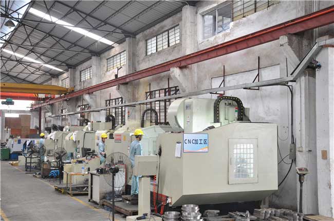
GUANGDONG RUIHUI INTELLIGENT TECHNOLOGY CO., LTD.
RUIHUI founded in 2000, the technology of automation periphery is from Japan. RUIHUI has been learning Japan and Germany technology, and using high standards of principle in the parts selection, for assembly process and spare parts, adhere to the requirements in accordance with the original design standard, and into each manufacturing process. In 20 years has accumulated experience and excellent design ability of Japanese engineers guided ruihui highly responsible for Industry and ruihui strong executive team, created a batch of well-known auto parts manufacturers, allowing them to reach the high level in same industry,and investment less.
Customer case
Manufacturing industry; the United States Lear, Honda factory, Ford factory, GAC Group, Chongqing Changan, Wuhan Shenlong, BMW Brilliance, FAW Volkswagen, Beijing Hyundai.
And other household appliances manufacturers; such as GREE, Haier, Midea, Chigo Air conditioning.
hardware manufacturers; such as the United States Southco, are Zhongtai industrial manufacturers success cooperation case.
RUIHUI QUALITY is not the best in the world, and the price is not the cheapest. But we can provide excellent products to help you defeat your competitors.
Products: Feeder machine, Straightener machine, Uncoiler machine, Decoiler with Straightener, 3 in 1 NC Straightener Feeder, Coil handling system, Transfer system, Robot System, to meet the market needs of customers, improve work efficiency, reduce the burden of enterprise management personnel, maintenance of production safety and the customer staff made a significant contribution.
At present the company to further develop the market, at the end of 2017, the total investment reached 30 million USD, plant area of more than 20 thousand square meters, in order to meet the demand on the market and lay a solid foundation after.
Why choose us?
1st,We have a high level of technical research and development team;
2nd,We can provide the design and planning of the whole plant to realize the turnkey project;
3rd, our philosophy: quality is the social responsibility;
4th,our products have been recognized by the market, in the major automotive OEM, home appliance industry, hardware industry has been applied;
5th,We have a highly effective after-sales service team and get customer approval.
Send your message to this supplier
You May Like

Metal Sheet Coil Decoiler Straightener Feeder For Press Machine
High Performance NC Metal Sheet Feeder Stamping Processing Automation Equipment
3 In 1 0.49Mpa Feeder Sheet Decoiling Machine
Vertical Material Rack Straightening Machine , Coil Feeder Metal Material Stamping
Metal Mold Material NC Servo Feeder Stamping Automatic Feeding Equipment
Punch Automation NC Decoiler Straightener Feeder Equipment Silicon Steel Sheet Stamping
NC 3 Phase 20m/Min 0.49Mpa Coil Handling Systems
High Efficiency Punch Automatic Feeder Stock Width 50~600mm , Robot Feeding Device
1000 Width Decoiler Straightener Feeder With Powerful Auxiliary Function
2.2kw 0.49Mpa Decoiler Straightener Feeder For Aluminum Sheet
RUIHUI AC 3.7KW 3 In 1 24m/Min Coil Feeder Straightener
Inquiry Cart
0